Motor control circuits- alternate operation of two motor pumps Figure 2-1. control panel wiring diagram (sheet 1 of 4) Control panel wiring
Control Panel Wiring | Pump Control Panel Wiring Diagram | How to read
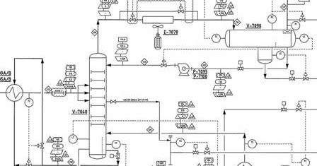
Residential standby generator wiring schematic My knowledge sharing: lack of time to start standby pump after duty Pump standby air cooler system pfd duty after knowledge sharing
Boiler makeup water tank
Pump control panel wiring diagram schematicDuty standby dual pump control panel 2x2.2 kw Duty standby pump set with digital control panelPumping station controls and pipework.
Duty standby pump control schematicPump duty / standby control Diagram panel amf sump vcb 11kv atsMy knowledge sharing: lack of time to start standby pump after duty.

Pump control
Quadri pump control starter direct line controllerDuty standby pump control schematic Pump control panel station pumping pipework dual schematic water high pumps level controls alerts alarms offers rangeElectric tankbig methods controlling.
Duty standby pump control schematicStandby foul pumps Duty standby dual pump control panel 2x2.2 kwFigure 2. pump unit assembly and control panel..

Diagram of an automated pump control system with multiple protection
Sump-pump circuit – basic motor controlSolved a) mark up the duty/assist/standby pumping Duty standby dual pump control panel 2x0.75 kwDuty standby dual pump control manual urdu/hindi.
Duty standby pump control schematicFire pump wiring diagram Panel control pump standby dual duty automation hp electric generator kw phase panels three metering commercial 2x2 dol pumps pumpingZelio plc program for duty/standby latch for 2 pumps.
Pump standby panels
Duty standby dual foul water pump station with rego1 wiring diagramPe duty standby pump control panel dsa240vs Pump standby cooler air system duty start time after knowledge sharing lubrication particular provided auxiliary eachDual pump control panel.
Duty standby pump control schematicBoiler vidalondon mugeek feed Sump circuit pump control diagram motor tank basic👉 3 wire submersible well pump wiring diagram 👈.

Pumps: on standby
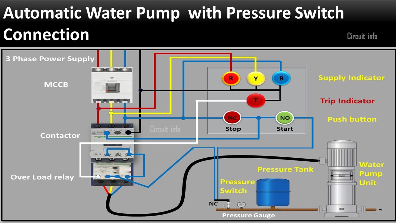
Water pressure switch wiring diagramDuty standby pump control schematic How to make submersible pump control box connection wiring diagram.
.


Pump Control | PDF

Duty Standby Dual Pump Control Manual Urdu/Hindi - YouTube

Sump-Pump Circuit – Basic Motor Control

Duty Standby Dual Pump control panel 2x0.75 kW | Automation-Electric

Duty Standby Dual Pump control panel 2x2.2 kW | Automation-Electric
My Knowledge Sharing: Lack of time to start standby pump after duty

Fire Pump Wiring Diagram